
Post Processing for Direct Metal Laser Melting (DMLM)
1. Loose Powder Removal
In DMLM, the powder that is not fused during the build will remain in loose powder form. The process of removing the loose powder is pretty straightforward, often performed with brushes or other hand tools. The loose powder that trapped in the internal features can be removed by compressed air or ultrasonic cleaning equipment.
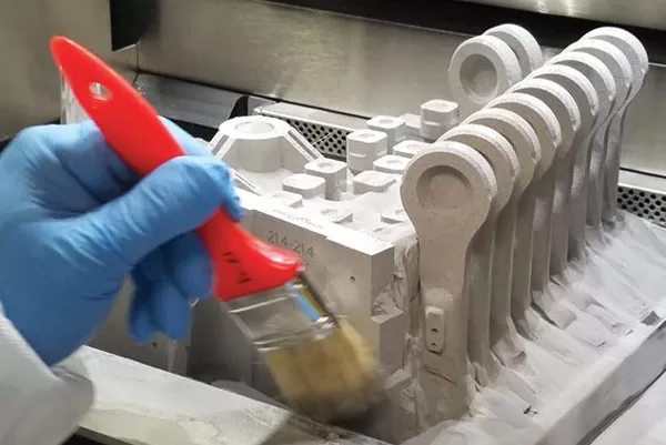
Removing loose powder by brushes in the AM machine build chamber
2. Thermal Processing
Stress Relief Treatment
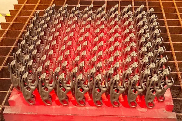
Heat treatment process to remove the internal stresses created in part during printing
In metal 3D printing, residual stress is inevitable. The rapid heating and cooling process during printing causes the internal stress induces in the metal parts. Hence, stress relieving should be carried out on all metal 3D printed products to minimize the residual stress. This process can reduce the risk of dimensional changes from warping when the part is removed from the build plate.
Hot Isostatic Pressing (HIP)
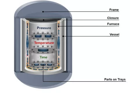
HIP Process to improve the density of the metal 3D printed parts
HIP is a form of heat treatment that utilizes high pressure and heat to improve the mechanical properties of the part. The density of the metal AM part can reach approximate 99.5% density, but not 100%. Hence, HIP can improve the density of the metal AM part by eliminating the internal and surface porosity.
Gas Nitriding

Schematic diagram of chemical reaction occurs during Gas Nitriding process
Gas Nitriding is a surface hardening process where nitrogen is added to the surface of the metal parts using dissociated ammonia as the source. This process temperature is normally in the range of 520°C. Gas Nitriding can improve the wear resistance and surface hardness of the metal 3D printed part.
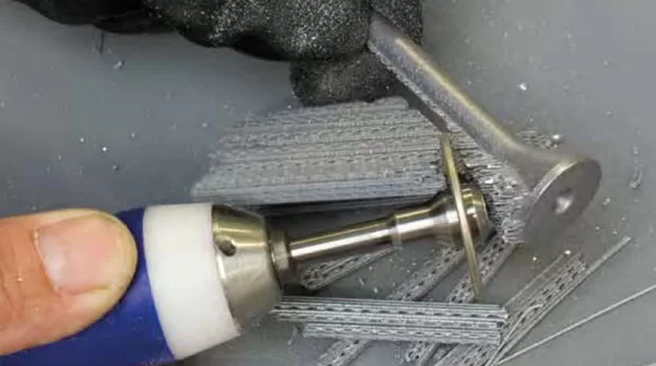
3. Supports Removal
Supports removal for metal 3D printed part is a very challenging and time-consuming task. Hence, optimizing the part orientation is a critical process during software preparation to reduce the creation of support generation as much as possible.
Supports removal always takes in place after stress relieving or other heat treatment process. The first step of support removal is to remove the parts and supports from the build plate.
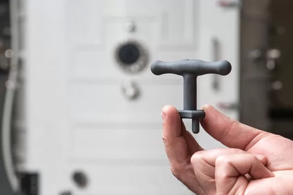
Supports can be removed manually by using simple hand tools such as pliers, hammers and other cutting and grinding tools.
Supports removal by hand tool
For any large surface contact area of metal 3D printed parts or supports with the build plate, wire EDM or a handsaw will be used to remove the parts and supports from the build plate.
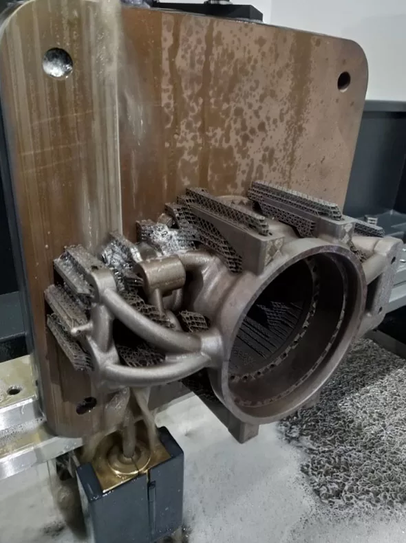
Wire EDM is used to separate metal 3D printed parts and supports from the build plate
4. Metal Surface Treatment
The surface finish of metal 3D printed part is very rough for some applications and hence it is necessary to improve it.
Surface roughness of the metal 3D printed part is normally determined by the powder particle size, layer thickness, build orientation and the presence of the supports. It is very difficult to specify the specified surface roughness for as-built surface roughness as top, bottom, angled and vertical surface finishes all have different surface roughness. The down-facing surface area and the area where supports are needed have rougher surface roughness.
Subtractive Finishing Process
The surface roughness of the metal 3D printed part can be improved via mechanical action (such as grinding, sanding, bead-blasting, shot peening, machining, tumbling, polishing) or chemical action combined with mechanical action (such as electro-polishing).
Media blasting (usually sand and glass bead) is used to clean the part and remove any residue powder that is still attached to the metal 3D printed part.
Machining is normally applied when the surface finish requirement is very high. When the areas of the part are known to require machining, extra allowances (normally 0.5mm) should be added during the software preparation. This is to make sure there are enough material allowances to be machined during CNC post machining. The CNC post machining for metal 3D printed part is very time consuming and costly, hence if the surface finish of the metal 3D printed part is not the priority in your project, it is always not recommended to go for this process. This process will extend the project lead-time and increase your cost.
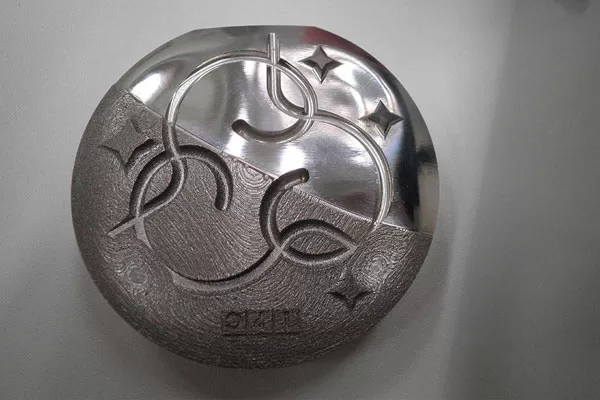
CNC machined finish vs As-built surface finish of metal 3D printed part
Additive Finishing Process
After the subtractive finishing process, the surface finish of the metal AM part can be further protected or improved aesthetically via additive finishing process.
Anodizing, electroplating, painting and physical vapor deposition (PVD) are the finishing techniques that can be applied to produce protective and decorative layer to metal 3D printed part.
Metal 3D printed mold insert coated in titanium nitride via PVD process to improve the wear and tear resistance